Sunday, June 8, 2014

CONFIGURING SITE TO SITE IPSEC VPN TUNNEL BETWEEN CISCO ROUTERS

Site-to-Site IPSec VPN Tunnels are used to allow the secure transmission of data, voice and video between two sites (e.g offices or branches). The VPN tunnel is created over the Internet public network and encrypted using a number of advanced encryption algorithms to provide confidentiality of the data transmitted between the two sites.
This article will show how to setup and configure two Cisco routers to create a permanent secure site-to-site VPN tunnel over the Internet, using the IP Security (IPSec) protocol. In this article we assume both Cisco routers have a static public IP address.  Readers interested in configuring support for dynamic public IP address endpoint routers can refer to our Configuring Site to Site IPSec VPN with Dynamic IP Endpoint Cisco Routers article.
IPSec VPN tunnels can also be configured using GRE (Generic Routing Encapsulation) Tunnels with IPsec. GRE tunnels greatly simply the configuration and administration of VPN tunnels and are covered in our Configuring Point-to-Point GRE VPN Tunnels article.  Lastly, DMVPNs – a new VPN trend that provide major flexibility and almost no administration overhead can also be examined by reading ourUnderstanding Cisco Dynamic Multipoint VPN (DMVPN),  Dynamic Multipoint VPN (DMVPN) Deployment Models & Architectures andConfiguring Cisco Dynamic Multipoint VPN (DMVPN) - Hub, Spokes , mGRE Protection and Routing - DMVPN Configuration articles.
ISAKMP (Internet Security Association and Key Management Protocol) and IPSec are essential to building and encrypting the VPN tunnel. ISAKMP, also called IKE (Internet Key Exchange), is the negotiation protocol that allows two hosts to agree on how to build an IPsec security association. ISAKMP negotiation consists of two phases: Phase 1 and Phase 2.  
Phase 1 creates the first tunnel, which protects later ISAKMP negotiation messages. Phase 2 creates the tunnel that protects data.  IPSec then comes into play to encrypt the data using encryption algorithms and provides authentication, encryption and anti-replay services.

IPSEC VPN REQUIREMENTS

To help make this an easy-to-follow exercise, we have split it into two steps that are required to get the Site-to-Site IPSec VPN Tunnel to work.
These steps are:
(1)  Configure ISAKMP (ISAKMP Phase 1)
(2)  Configure IPSec  (ISAKMP Phase 2, ACLs, Crypto MAP)
Our example setup is between two branches of a small company, these are Site 1 and Site 2. Both the branch routers connect to the Internet and have a static IP Address assigned by their ISP as shown on the diagram:
 cisco-routers-s2s-ipsec-vpn-1
Site 1 is configured with an internal network of 10.10.10.0/24, while Site 2 is configured with network 20.20.20.0/24. The goal is to securely connect both LAN networks and allow full communication between them, without any restrictions.

CONFIGURE ISAKMP (IKE) - (ISAKMP PHASE 1)

IKE exists only to establish SAs (Security Association) for IPsec. Before it can do this, IKE must negotiate an SA (an ISAKMP SA) relationship with the peer.
To begin, we’ll start working on the Site 1 router (R1).
First step is to configure an ISAKMP Phase 1 policy:
R1(config)#  crypto isakmp policy 1
R1(config-isakmp)# encr 3des
R1(config-isakmp)# hash md5
R1(config-isakmp)# authentication pre-share
R1(config-isakmp)# group 2
R1(config-isakmp)# lifetime 86400

The above commands define the following (in listed order):
3DES - The encryption method to be used for Phase 1.
MD5 - The hashing algorithm
Pre-share - Use Pre-shared key as the authentication method
Group 2 - Diffie-Hellman group to be used
86400 – Session key lifetime. Expressed in either kilobytes (after x-amount of traffic, change the key) or seconds. Value set is the default value.
We should note that ISAKMP Phase 1 policy is defined globally. This means that if we have five different remote sites and configured five different ISAKMP Phase 1 policies (one for each remote router), when our router tries to negotiate a VPN tunnel with each site it will send all five policies and use the first match that is accepted by both ends.
Next we are going to define a pre shared key for authentication with our peer (R2 router) by using the following command:
R1(config)# crypto isakmp key firewallcx address 1.1.1.2
The peer’s pre shared key is set to firewallcx and its public IP Address is 1.1.1.2. Every time R1 tries to establish a VPN tunnel with R2 (1.1.1.2), this pre shared key will be used.


CONFIGURE IPSEC

To configure IPSec we need to setup the following in order:
- Create extended ACL
- Create IPSec Transform
- Create Crypto Map
- Apply crypto map to the public interface
Let us examine each of the above steps.


CREATING EXTENDED ACL

Next step is to create an access-list and define the traffic we would like the router to pass through the VPN tunnel.  In this example, it would be traffic from one network to the other, 10.10.10.0/24 to 20.20.20.0/24.  Access-lists that define VPN traffic are sometimes calledcrypto access-list or interesting traffic access-list.
R1(config)# ip access-list extended VPN-TRAFFIC
R1(config-ext-nacl)# permit ip 10.10.10.0 0.0.0.255 20.20.20.0 0.0.0.255


CREATE IPSEC TRANSFORM (ISAKMP PHASE 2 POLICY)

Next step is to create the transform set used to protect our data. We’ve named this TS:
R1(config)# crypto ipsec transform-set TS esp-3des esp-md5-hmac
The above command defines the following:  
- ESP-3DES - Encryption method
- MD5 - Hashing algorithm

CREATE CRYPTO MAP

The Crypto map is the last step of our setup and connects the previously defined ISAKMP and IPSec configuration together:
R1(config)# crypto map CMAP 10 ipsec-isakmp
R1(config-crypto-map)# set peer 1.1.1.2
R1(config-crypto-map)# set transform-set TS
R1(config-crypto-map)# match address VPN-TRAFFIC
We’ve named our crypto map CMAP. The ipsec-isakmp tag tells the router that this crypto map is an IPsec crypto map. Although there is only one peer declared in this crypto map (1.1.1.2), it is possible to have multiple peers within a given crypto map.

APPLY CRYPTO MAP TO THE PUBLIC INTERFACE

The final step is to apply the crypto map to the outgoing interface of the router. Here, the outgoing interface is FastEthernet 0/1.
R1(config)# interface FastEthernet0/1
R1(config- if)# crypto map CMAP
Note that you can assign only one crypto map to an interface.
As soon as we apply crypto map on the interface, we receive a message from the router  that confirms isakmp is on: “ISAKMP is ON”.
At this point, we have completed the IPSec VPN configuration on the Site 1 router.
We now move to the Site 2 router to complete the VPN configuration. The settings for Router 2 are identical, with the only difference being the peer IP Addresses and access lists:
R2(config)# crypto isakmp policy 1
R2(config-isakmp)# encr 3des
R2(config-isakmp)# hash md5
R2(config-isakmp)# authentication pre-share
R2(config-isakmp)# group 2
R2(config-isakmp)# lifetime 86400
R2(config)# crypto isakmp key firewallcx address 1.1.1.1
R2(config)# ip access-list extended VPN-TRAFFIC
R2(config-ext-nacl)# permit ip 20.20.20.0 0.0.0.255 10.10.10.0 0.0.0.255
 
R2(config)# crypto ipsec transform-set TS esp-3des esp-md5-hmac
R2(config)# crypto map CMAP 10 ipsec-isakmp
R2(config-crypto-map)# set peer 1.1.1.1
R2(config-crypto-map)# set transform-set TS
R2(config-crypto-map)# match address VPN-TRAFFIC
R2(config)# interface FastEthernet0/1
R2(config- if)# crypto map CMAP


NETWORK ADDRESS TRANSLATION (NAT) AND IPSEC VPN TUNNELS

Network Address Translation (NAT) is most likely to be configured to provide Internet access to internal hosts. When configuring a Site-to-Site VPN tunnel, it is imperative to instruct the router not to perform NAT (deny NAT) on packets destined to the remote VPN network(s).
This is easily done by inserting a deny statement at the beginning of the NAT access lists as shown below:
For Site 1’s router:
R1(config)# ip nat inside source list 100 interface fastethernet0/1 overload
R1(config)# access-list 100 remark -=[Define NAT Service]=-
R1(config)# access-list 100 deny ip 10.10.10.0 0.0.0.255 20.20.20.0 0.0.0.255
R1(config)# access-list 100 permit ip 10.10.10.0 0.0.0.255 any
R1(config)# access-list 100 remark

And Site 2’s router:
R2(config)# ip nat inside source list 100 interface fastethernet0/1 overload
R2(config)# access-list 100 remark -=[Define NAT Service]=-
R2(config)# access-list 100 deny ip 20.20.20.0 0.0.0.255 10.10.10.0  0.0.0.255
R2(config)# access-list 100 permit ip 20.20.20.0 0.0.0.255 any
R2(config)# access-list 100 remark


BRINGING UP AND VERIFYING THE VPN TUNNEL

At this point, we’ve completed our configuration and the VPN Tunnel is ready to be brought up.  To initiate the VPN Tunnel, we need to force one packet to traverse the VPN and this can be achieved by pinging from one router to another:
R1# ping 20.20.20.1 source fastethernet0/0
Type escape sequence to abort.
Sending 5, 100-byte ICMP Echos to 20.20.20.1, timeout is 2 seconds:
Packet sent with a source address of 10.10.10.1
.!!!!
Success rate is 80 percent (4/5), round-trip min/avg/max = 44/47/48 ms


The first ping received a timeout, but the rest received a reply, as expected. The time required to bring up the VPN Tunnel is sometimes slightly more than 2 seconds, causing the first ping to timeout.
To verify the VPN Tunnel, use the show crypto session command:
R1# show crypto session
Crypto session current status
Interface: FastEthernet0/1
Session status: UP-ACTIVE    
Peer: 1.1.1.2 port 500
  IKE SA: local 1.1.1.1/500 remote 1.1.1.2/500 Active
  IPSEC FLOW: permit ip 10.10.10.0/255.255.255.0 20.20.20.0/255.255.255.0
        Active SAs: 2, origin: crypto map


Thursday, June 5, 2014

Configure Windows Server 2008 as a RADIUS Server with MS-CHAP v2 Authentication


Overview
 
This article describes how you can configure Windows Server 2008 as a RADIUS Server and integrate it with Cyberoam.
 
Scenario
Configure Windows Server 2008 as RADIUS Server with MS-CHAP v2 authentication and integrate Cyberoam as a RADIUS Client.
 
Configuration
You can configure Windows Server 2008 by following the steps given below. Configuration is to be done from Windows Server Manager.
Note:
Prior to configuration, make sure that:
 
-         You have setup Active Directory Services, and Network Policies and Access Services (NPS) Roles.
-         The NPS Roles are integrated with the Active Directory.
 

Step 1: Add Cyberoam as RADIUS Client

·         Login to Windows Server 2008 using Administrator profile.
·         Go to Start à Administrative Tools à Server Manager .
·         On the left panel, expand Roles à Network Policy and Access Services à NPS (Local) à RADIUS Clients and Servers and right click onRADIUS Clients. Click New RADIUS Client to create a new client according to parameters given below.


Parameter Description
Parameter
Value
Description
Friendly name
Cyberoam
Name to identify the RADIUS Client
Address (IP or DNS)
172.16.16.1
Address of the RADIUS Client. Here, we have specified Cyberoam LAN IP Address.
Vendor name
RADIUS Standard
Specify the RADIUS Client Vendor name from the list
Shared secret
Manual
Select whether shared secret is to be manually set or auto-generated.
Secret
cyberoam
Specify the secret


Click OK to create the RADIUS Client.


Step 2: Configure Network Policies
On the left panel, expand Roles à Network Policy and Access Services à NPS (Local)à Policies and right-click Network Policies. Click Newto open the New Network Policy Wizard.


·         Mention Policy Name and click Next.


·         Click Add under Specify Conditions to add conditions that determine whether this network policy is evaluated for a connection request. Here, we have added 2 conditions: 
        -         User Group as Marketing
        -         NAS IP address as Cyberoam LAN IP address


·         The Select Condition Window opens. Select the first type of condition as User Groups and click Add.


·         The User Groups Window opens. Click Add Groups... to add user groups.


·         The Select Group Window opens. Mention the Group Marketing under Enter the object name to select and click OK.


·         The user group condition is added. Now click Add... again to add the second condition.


·         Under Gateway section, select NAS IPv4 Address to specify the IP address of the Network Access Server (NAS) and click Add.


·         Mention Cyberoam’s LAN IP address as NAS address.


·         Click OK to save settings. The following screen is displayed showing configured conditions. Click Next.


·         The Specify Access Permission screen appears. Select Access granted and click Next.


·         The Configure Authentication Methods screen appears. Select the authentication as Microsoft Encrypted Authentication version 2 (MS-CHAP v2) and Unencrypted authentication (PAP, SPAP). Click Next.
 
      Note:
      PAP authentication method is required because Cyberoam uses PAP to test connectivity with the RADIUS Server. 


·         The Configure Constraints screen appears. Retain default constraints. Click Next.


·         The Configure Settings screen appears. Retain default settings. Click Next.
If you want to configure Tight Integration between RADIUS Server and NAS, then add Filter ID as one of the attributes by clicking Add.... 


·         The Completing New Network Policy appears which displays the summary of the policy you have configured. Click Finish to create the policy.


Step 3: Allow Network Access to Users

Once Network Policies are configured, ensure that users, belonging to the User Group defined in the Policy, are allowed network access. Here, we have enabled network
access of a user named John Smith who belongs to the CYBEROAM"Marketing User Group. You can enable network access by following instructions given below. 
 
On the left panel, expand through Roles à Active Directory Domain Services à Active Directory Users and Computers à cyberoam.localand click Users  
to display a list of existing users. Right click user John Smith and click Properties from the pop up.


In the Properties window, switch to Dial-in tab, under Network Access Permission select Allow access to allow network access to user John Smith.


Click OK to save settings.

Step 4: Integrate Cyberoam with RADIUS Server

Integrate Cyberoam with the RADIUS Server configured above such that it uses the Server for user authentication. To know how you can configure Cyberoam
to use RADIUS Server, refer to the article Configure Cyberoam to use RADIUS Server for Authentication.
 
The above configuration configures the Windows Server 2008 as a RADIUS Server with Cyberoam as the Client. Cyberoam uses this RADIUS Server for user authentication.

Monday, April 21, 2014

Install Nagios on RHEL/CentOS 6.x/5.x and Fedora 19/18/17

Nagios is an awesome Open Source monitoring tool, its provides you more comprehensive monitoring environment to always keep an eye on your all machines / networks whether you are in a your data center or just your small labs.
With Nagios, you can monitor your remote hosts and their services remotely on a single window. It shows warnings and indicates if something goes wrong in your servers which eventually helps us to detect some problems before they occur. It helps us to reducedowntime and business losses.
Recently, Nagios released its latest versions Nagios 4.0.1 on 15th October 2013, and its latest stable release of Nagios plugins 1.5.
This article is intended to guide you with easy instructions on how to install latest Nagios 4.0.1 from source (tarball) on RHEL 6.4/6.3/6.2/6.1/6/5.8, CentOS 6.4/6.3/6.2/6.1/6/5.8and Fedora 19,18,17,16,15,14,13,12 distributions. Within 30 minutes you will be monitoring your local machine, no any advanced installation procedure only basic installation that will work 100% on most of the today’s Linux servers.
Please Note: The installation instructions were shown in here are written based on CentOS 6.4 Linux distribution.

Installing Nagios 4.0.1 and Nagios Plugin 1.5

If you follow these instructions correctly, you will end up with following information.
  1. Nagios and its plugins will be installed under /usr/local/nagios directory.
  2. Nagios will be configured to monitor few services of your local machine (Disk Usage, CPU Load, Current Users, Total Processes, etc.)
  3. Nagios web interface will be available at http://localhost/nagios

Step 1: Install Required Dependencies

We need to install Apache, PHP and some libraries like gcc, glibc, glibc-common and GDlibraries and its development libraries before installing Nagios 4.0.1 with source. And to do so we can use yum default package installer.
[root@tecmint]# yum install -y httpd php gcc glibc glibc-common gd gd-devel make net-snmp  (RedHat / CentOS)

Step 2: Create Nagios User and Group

Create a new nagios user and nagcmd group account and set a password.
[root@tecmint]# useradd nagios
[root@tecmint]# groupadd nagcmd
Next, add both the nagios user and the apache user to the nagcmd group.
[root@tecmint]# usermod -G nagcmd nagios
[root@tecmint]# usermod -G nagcmd apache

Step 3: Download Nagios Core 4.0.1 and Nagios Plugin 1.5

Create a directory for your Nagios installation and all its future downloads.
[root@tecmint]# mkdir /root/nagios
[root@tecmint]# cd /root/nagios
Now download latest Nagios Core 4.0.1 and Nagios plugins 1.5 packages with wget command.
[root@tecmint nagios~]# wget http://prdownloads.sourceforge.net/sourceforge/nagios/nagios-4.0.1.tar.gz
[root@tecmint nagios~]# wget https://www.nagios-plugins.org/download/nagios-plugins-1.5.tar.gz

Step 4: Extract Nagios Core and its Plugins

We need to extract downloaded package with tar command as follows.
[root@tecmint nagios~]# tar –xvf nagios-4.0.1.tar.gz
[root@tecmint nagios~]# tar –xvf nagios-plugins-1.5.tar.gz
When you extract these tarballs with tar command, two new folders will appear in that directory.
[root@tecmint nagios ~]# ll
total 3712
18 root root 4096 Oct 17 03:28 nagios-4.0.1
drwxrwxr-x
rw-r--r-- 1 root root 1695367 Oct 15 19:49 nagios-4.0.1.tar.gz
-drwxr-xr-x 15 200 300 4096 Oct 14 10:18 nagios-plugins-1.5
-rw-r--r-- 1 root root 2428258 Oct 2 11:27 nagios-plugins-1.5.tar.gz

Configure Nagios Core

Now, first we will configure Nagios Core and to do so we need to go to Nagios directory and run configure file and if everything goes fine, it will show the output in the end as sample output. Please see below.
[root@tecmint nagios~]# cd nagios-4.0.1
[root@tecmint nagios-4.0.1 ]# ./configure --with-command-group=nagcmd
Sample output:
Nagios executable: nagios
Nagios user/group: nagios,nagios
Command user/group: nagios,nagcmd
stall ${prefix}: /usr/local/na
Event Broker: yes I ngios Install ${includedir}: /usr/local/nagios/include/nagios
lt directory: ${prefix}/var/spool/checkresults
Lock file: ${prefix}/var/nagios.lock Check res u Init directory: /etc/rc.d/init.d Apache conf.d directory: /etc/httpd/conf.d
face Options: ----------------------
Mail program: /bin/mail Host OS: linux-gnu Web Inte r-- HTML URL: http://localhost/nagios/ CGI URL: http://localhost/nagios/cgi-bin/
' to compile the main program and CGIs.
Traceroute (used by WAP): /bin/traceroute Review the options above for accuracy. If they look okay, type 'make al
l
Now, after configuring we need to Compile and install all the binaries with make command and make install command will install all the needed libraries in your machine and we can proceed further.
[root@tecmint nagios-4.0.1 ]# make all
[root@tecmint nagios-4.0.1 ]# make install
Sample output:
*** Main program, CGIs and HTML files installed ***
ou can continue with installing Nagios as follows (type 'make'
Ywithout any arguments for a list of all possible options):
etc/rc.d/init.d
make install-init - This installs the init script in /make install-commandmode - This installs and configures permissions on the
- This installs sample config files in /usr/local/na
directory for holding the external command file make install-config
gios/etc
Following command will install the init scripts for Nagios.
[root@tecmint nagios-4.0.1 ]# make install-init
To make nagios work from command line we need to install command-mode.
[root@tecmint nagios-4.0.1 ]# make install-commandmode
Next, install sample nagios files, please run following command.
[root@tecmint nagios-4.0.1 ]# make install-config
Sample output:
/usr/bin/install -c -m 775 -o nagios -g nagios -d /usr/local/nagios/etc
/usr/bin/install -c -m 775 -o nagios -g nagios -d /usr/local/nagios/etc/objects
/usr/bin/install -c -b -m 664 -o nagios -g nagios sample-config/nagios.cfg /usr/local/nagios/etc/nagios.cfg
/usr/bin/install -c -b -m 664 -o nagios -g nagios sample-config/cgi.cfg /usr/local/nagios/etc/cgi.cfg
ource.cfg /usr/bin/install -c -b -m 664 -o nagios -g nagios sample-config/template-object/templates.cfg /usr/lo
/usr/bin/install -c -b -m 660 -o nagios -g nagios sample-config/resource.cfg /usr/local/nagios/etc/re scal/nagios/etc/objects/templates.cfg /usr/bin/install -c -b -m 664 -o nagios -g nagios sample-config/template-object/commands.cfg /usr/local/nagios/etc/objects/commands.cfg
s -g nagios sample-config/template-object/timeperiods.cfg /usr/local/nagios/etc/objects/timeperiods.cfg /usr/bin/install -c -b -m 664 -
/usr/bin/install -c -b -m 664 -o nagios -g nagios sample-config/template-object/contacts.cfg /usr/local/nagios/etc/objects/contacts.cfg /usr/bin/install -c -b -m 664 -o nagi oo nagios -g nagios sample-config/template-object/localhost.cfg /usr/local/nagios/etc/objects/localhost.cfg /usr/bin/install -c -b -m 664 -o nagios -g nagios sample-config/template-object/windows.cfg /usr/local/nagios/etc/objects/windows.cfg
/etc/objects/switch.cfg *** Config files installed *** Remember, these are *SAMPLE* config files. You'll need to read the document
/usr/bin/install -c -b -m 664 -o nagios -g nagios sample-config/template-object/printer.cfg /usr/local/nagios/etc/objects/printer.cfg /usr/bin/install -c -b -m 664 -o nagios -g nagios sample-config/template-object/switch.cfg /usr/local/nagio sation for more information on how to actually define
services, hosts, etc. to fit your particular needs.

Step 5: Customizing Nagios Configuration

Open the “contacts.cfg” file with your choice of editor and set the email addressassociated with the nagiosadmin contact definition to receiving email alerts.
# vi /usr/local/nagios/etc/objects/contacts.cfg
Sample Output
###############################################################################
###############################################################################
#
# # CONTACTS # ################################################################ ##############
################################################################ # Just one co
############## #ntact defined by default - the Nagios admin (that's you)
from the 'generic-contact' # template which is defined elsewhere. define contact{
# This contact definition inherits a lot of default value s contact_name nagiosadmin ; Short name of user
ues from generic-contact template (defined above) alias Nagios Admin ; Full name of user
use generic-contact ; Inherit default va l
email tecmint@tecmint.com ; *** CHANGE THIS TO YOUR EMAIL ADDRESS ****
}

Step 6: Install and Configure Web Interface for Nagios

We are done with all configuration in the backend, now we will configure Web Interface For Nagios with following command. The below command will Configure Web interface for Nagios and a web admin user will be created “nagiosadmin”.
[root@tecmint nagios-4.0.1 ]# make install-webconf
In this step, we will be creating a password for “nagiosadmin”. After executing this command, please provide a password twice and keep it remember because this password will be used when you login in the Nagios Web interface.
[root@tecmint nagios-4.0.1]# htpasswd -s -c /usr/local/nagios/etc/htpasswd.users nagiosadmin
New password: Re-type new password:
Adding password for user nagiosadmi n
Restart Apache to make the new settings take effect.
[root@tecmint ]# service httpd start (On RedHat / CentOS)
[root@tecmint ]# systemctl start httpd.service (On Fedora)

Step 7: Compile and Install Nagios Plugin

We have downloaded nagios plugins in /root/nagios, Go there and configure and install it as directed below.
[root@tecmint nagios]# cd /root/nagios
[root@tecmint nagios]# cd nagios-plugins-1.5
[root@tecmint nagios]# ./configure --with-nagios-user=nagios --with-nagios-group=nagios
[root@tecmint nagios]# make
install
[root@tecmint nagios]# make

Step 8: Verify Nagios Configuration Files

Now we are all done with Nagios configuration and its time to verify it and to do so please insert following command. If everything goes smooth it will show up similar to below output.
[root@tecmint nagios]# /usr/local/nagios/bin/nagios -v /usr/local/nagios/etc/nagios.cfg
Sample Output
/usr/bin/install -c -m 644 sample-config/httpd.conf /etc/httpd/conf.d/nagios.conf
*** Nagios/Apache conf file installed ***
nagios/etc/nagios.cfg ... ... Total Warnings: 0 Total Errors: 0
/usr/local/nagios/bin/nagios -v /usr/local
/

Step 9: Add Nagios Services to System Startup

To make Nagios work across reboots, we need to add nagios and httpd with chkconfigcommand.
[root@tecmint ]# chkconfig --add nagios
[root@tecmint ]# chkconfig --level 35 nagios on
[root@tecmint ]# chkconfig --add httpd
ttpd on
[root@tecmint ]# chkconfig --level 35 h
Restart Nagios to make the new settings take effect.
[root@tecmint ]# service nagios start (On RedHat / CentOS)
[root@tecmint ]# systemctl start nagios.service (On Fedora)

Step 10: Login to the Nagios Web Interface

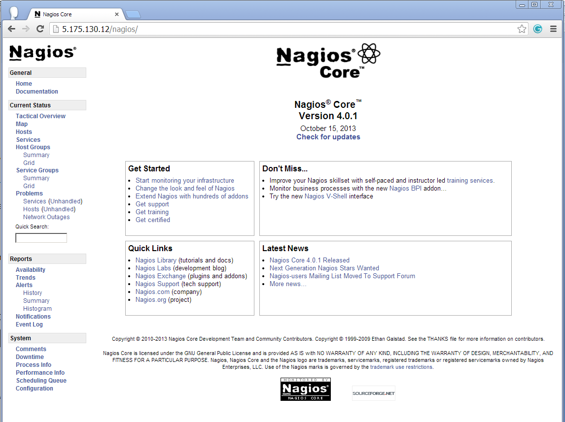
Your nagios is ready to work, please open it in your browser with “http://Your-server-IP-address/nagios” or “http://FQDN/nagios” and Provide the username “nagiosadmin” andpassword.
Nagios Login
Nagios Login
Nagios Web Interface
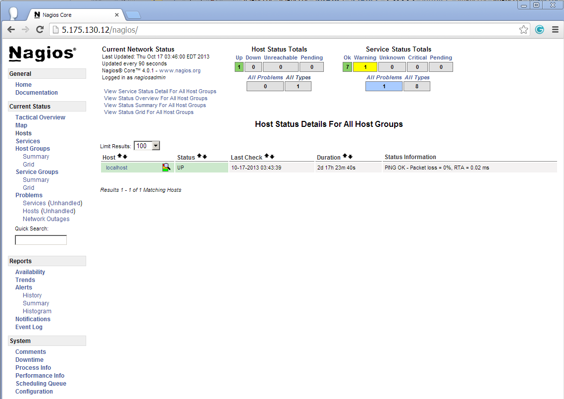
Host View
Nagios Host View
Nagios Host View
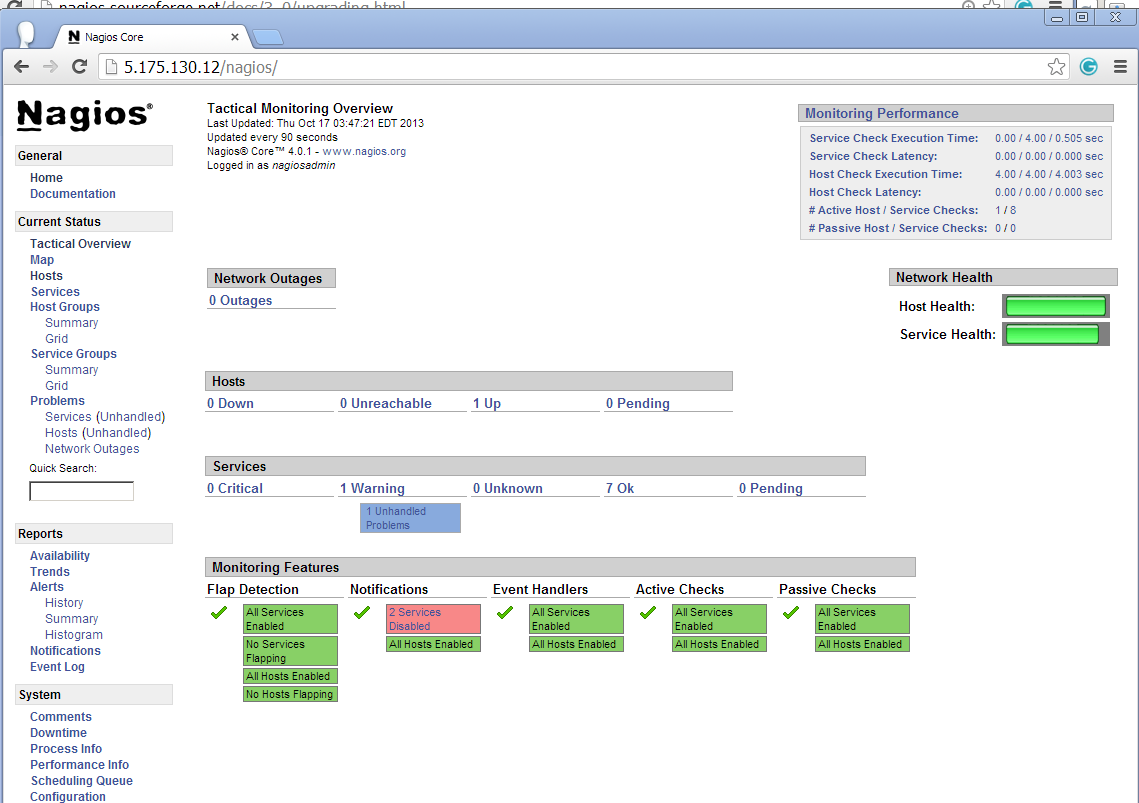
Nagios Overview
Nagios Overview
Nagios Overview
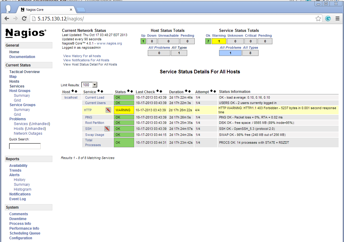
Service View
Nagios Services
Nagios View Services
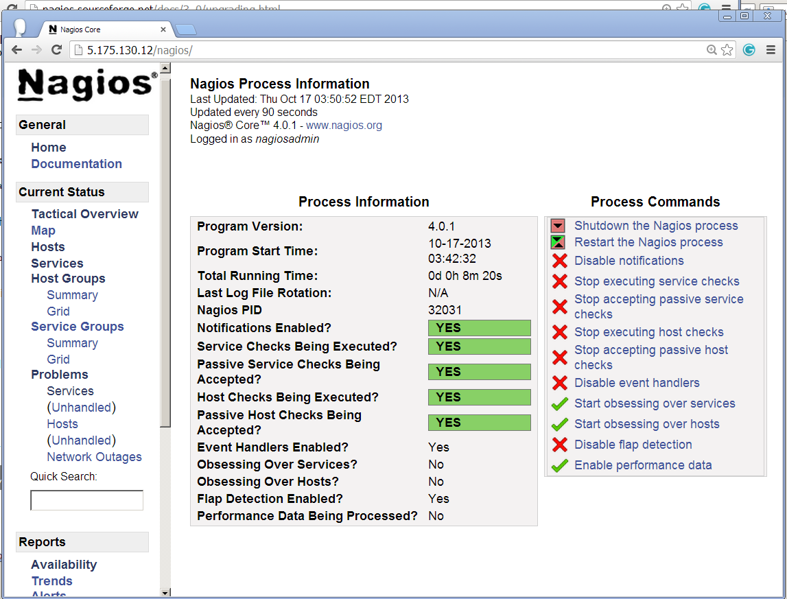
Process View
Nagios Process View
Process View
Congratulations! You’ve successfully installed and configured Nagios and its Plugins. You’ve just begin your journey into monitoring.

Upgrade Nagios 3.x to Nagios 4.0.1

If you are already running an older version of Nagios, you can upgrade it anytime. To do so, you just need to download the latest tar archive of it and configure it as shown below.
[root@tecmint ]# service nagios stop
[root@tecmint ]# tar –zxvf nagios-4.0.1.tar.gz
[root@tecmint ]# cd nagios-4.0.1
t@tecmint ]# make all [root@
[root@tecmint ]# ./configure [ro otecmint ]# make install
nagios start
[root@tecmint ]# service
That’s it for now, in my upcoming articles, I will show you how to add Linux, Windows,Printers, Switches and Devices to Nagios monitoring Server. If you’re having any trouble while installing, please do contact us via comments. Till then stay tuned and connected toTecmint and don’t forget to Like and Share us to spread around.
http://www.tecmint.com/install-nagios-in-linux/